Aug 30, 2023
Interesting Facts
Although, LEDs have in recent times become immensely popular it was interesting to find out that LEDs have been around for more than half a century. The LED invented was in 1962 by 33-year-old Nick Holonyak Jr. a General Electric scientist. It is important to understand that LED is made up of diodes.
Therefore, Light Emitting Diodes (LED) are semiconductor devices. The diode allows current to flow in one direction and does not allow reverse currents. LEDs function as a diode in addition to its ability to emit light. Blinking LEDs is a simple project but, it has a wide range of great applications such as:
A dancing LED circuit is used as a visual sign indication on any highway
The LED blinking circuit can be used to signal help
LED blinking can be instrumental as a flashing beacon
Blinking LED can be used as a vehicle indicator
For tutorial 2 we will be blinking LED with Arduino from the list provided we have seen the numerous applications of LED applications and now we know why LED blinking is important.
Materials Needed
Arduino UNO ( Also Arduino IDE)
LEDs
Resistors 220Ω (led resistor)
Jumper Wires
Breadboard

Connection Procedure
Step 1: Connect the power and ground rails
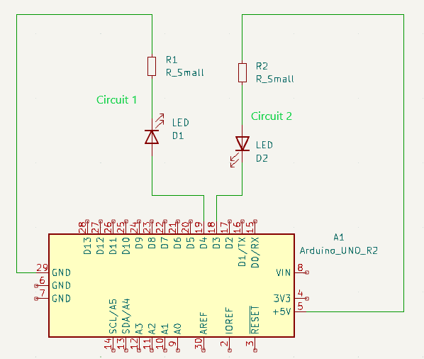
Step 2: Wire up the first circuit, where the LED anode (the long leg) is connected to Pin 4 and the resistor is connected to the ground rail.
Step 3: Wire up the second circuit, where the LED cathode (the short leg) is connected to the short leg to pin 3 and the resistor to the 5V rail.

Setup Explanation
The Circuit goes as follows:
In circuit 1 the wire connects from the ground to the 220Ω resistor that is connected to the anode end of the LED to pin 4 of the Arduino.
In circuit 2 the wire connects from the 5V to the 220Ω resistor that is connected to the cathode end of the LED to pin 3 of the Arduino.
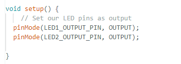
The code for the blinking LEDs connected to pins 3 and 4 goes as follows:
The code is an important part of how blinking LEDs work.
Pin 4 circuit (LED circuit 1) that will turn ON using digitalWrite(3, HIGH) on the other hand Pin 3 circuit (LED circuit 2) will turn OFF using digitalWrite(4, HIGH).
Why? Recall current always flows from a high voltage potential to a low voltage potential.
When Pin 4 is HIGH (5V) therefore, there is a voltage difference between Pin 4 and the ground thus, current flows from Pin 4 to the ground. When Pin 3 is HIGH (5V) conversely there is no voltage difference this ensures that no current flows from Pin 3 to 5V.
Code: Blinking Pins 3 and 4

Initialization

Blink Code Loop

Compile, Upload and Run Code
Video: This video can assist in guiding you to start on the alternative blinking LEDs on a step-by-step basis and with a better explanation.
