Sep 4, 2023
For this tutorial, we are going to look at a simple servo motor project. Before we delve into the project we need to get crucial insights into what is a Servo Motor.
A Servo Motor refers to a motor that can rotate with exceptional precision. Servo motors consist of circuits that can provide feedback on the current position of the motor shaft enabling servo motors to rotate with great precision. Motors play an instrumental role in completing powerful tasks as they can convert electrical energy to mechanical energy. Servo motors and stepper motors have distinct advantages in availing common solutions to ensure motion control projects.
Servo motors turn to specified positions where the servo arm can turn 180 degrees. Servo motors were initially used in remote control to control cars, and flaps on a remote control plane. Over time they have found use in robotics as servo motors tend to be lighter than stepper motors. Therefore, the light weight of the stepper motor provide robotics as well as the robotic arm more flexibility to ensure a balance when moving around. The servo motor consists of in-built motors, a feedback circuit, and a motor driver. Therefore, the servo requires a power line ground and control pin.
Let’s get into the servo project; The project with the servo motor includes the following requirements:
Materials Needed (For servo project Arduino)
Servo motors
Jumper wires
Arduino board connected to a computer

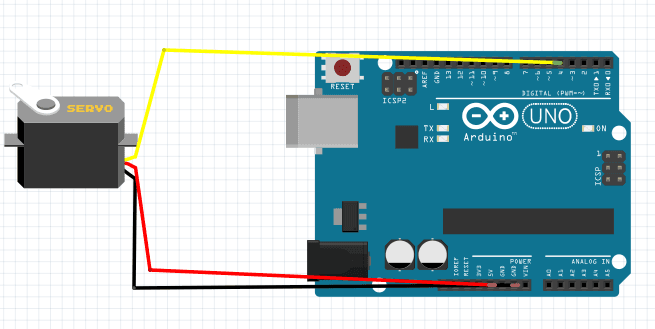
Connecting a Servo motor to the Arduino
The servo motor has a female connector with three pins. The darkest or even black one is usually the ground connecting this to the ground of the Arduino’s GND.
Connect the power cable that in all standards should be red to 5V on the Arduino
Connect the remaining line on the servo connector to a digital in the Arduino
CODE:
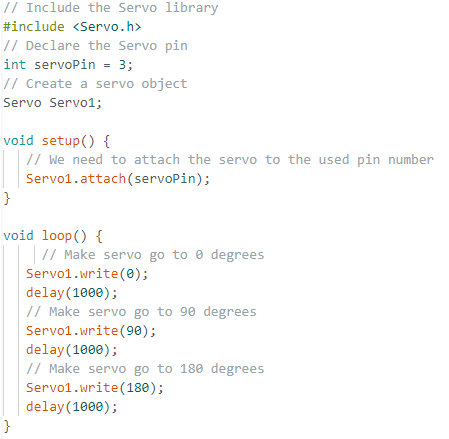
The following code will turn a servo motor to 0 degrees, wait for 1 second then turn it to 90 degrees wait one more second turn it to 180 degrees then go back:

The code simply declares the servo object and then initializes the servo by using the Servo.attach()function. We shouldn’t forget to include the servo library in the servo library. In the loop() we set the servo to 0 degrees, wait then set it to 90 degrees and later 180 degrees
SETUP EXPLANATION
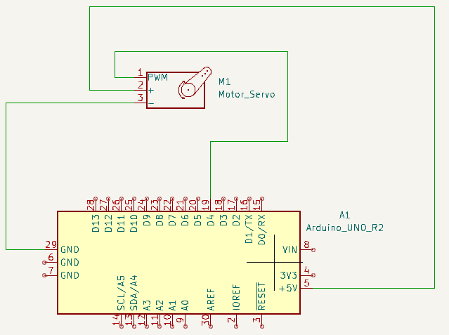
The diagram below illustrates a schematic diagram for a servo project using Arduino.

Servos work by receiving a position from the Arduino using one input Pin. The servo internally comprises a motor driver and a feedback circuit to ensure the servo arm reaches the desired position
Servo receive a square wave similar to PWM, each cycle in the signal lasts for 20 milliseconds and most of the time the value is LOW
At the beginning of each cycle, the signal is HIGH for a time between 1 and 2 milliseconds. At 1 milliseconds it represents 0 degrees and at 2 milliseconds it represents 180 degrees. The values in between range from 0 to 180. This is a good and reliable method, the graphics make it a little easier to understand.
Remember that using the Servo library automatically disables PWM functionality on PWM pins 9 and 10 on the Arduino UNO and similar boards.
To use more than one servo declare multiple servo objects
Attach different pins to each servo individually

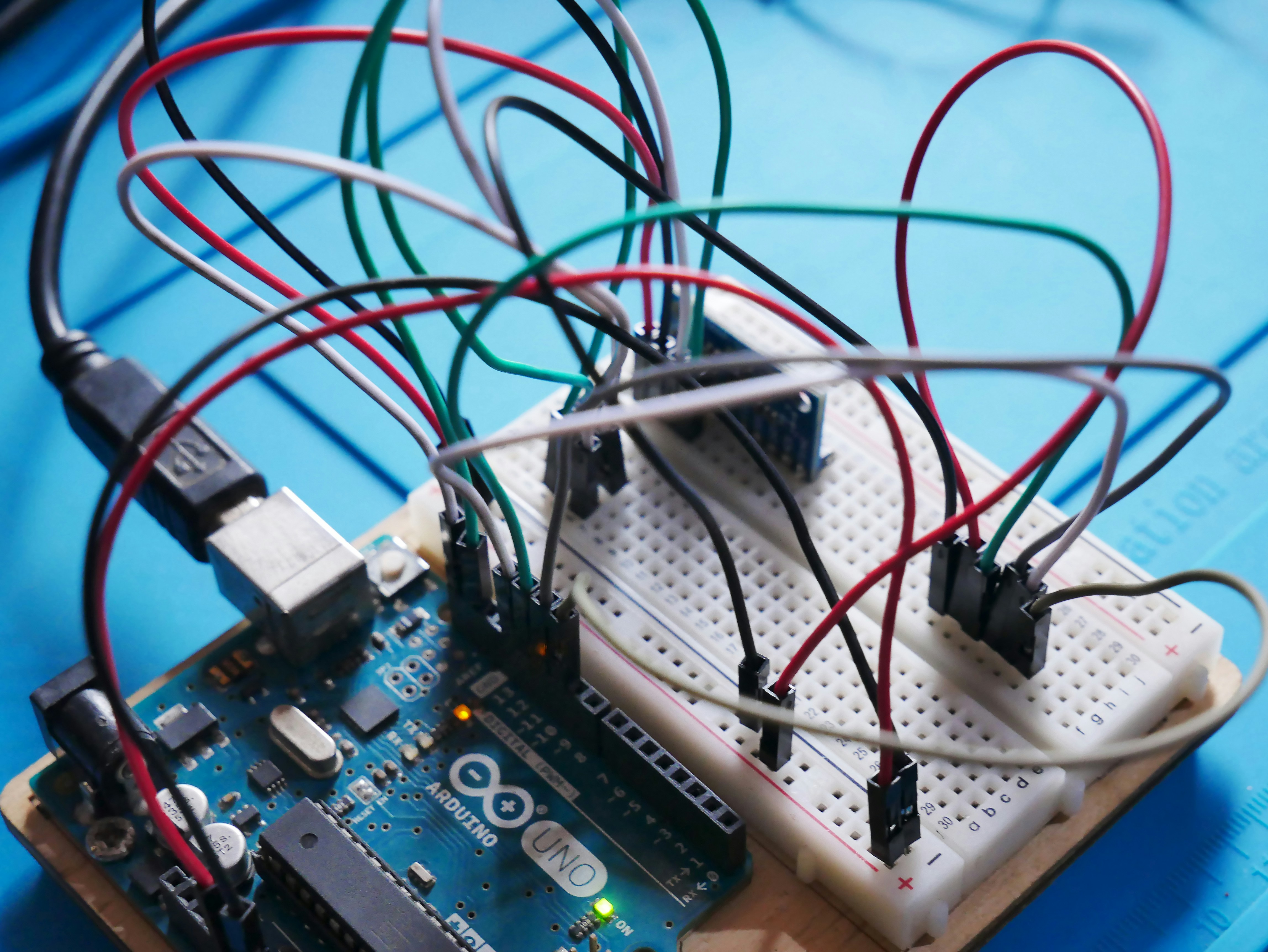
Connection-wise the grounds from the servos go to GND on the Arduino the servo power to 5V or VIN(Depending on the power input). In the end, each signal line has to be connected to a different digital pin. Contrary to popular belief Servo doesn’t need to be controlled by PWM pins, Any digital pin will work
VIDEO: The video includes a project with a servo motor. The video provides crucial insights into the various workings of the servo motors using different circuits including some that have a servo controller.
